I2C Pressure Sensor | Pa6DC

I2C Protocol Output, Short Lead Times, UK-Made

Description

Applied Measurements I2C pressure sensor Pa6DC uses an I2C (Inter-Integrated Circuit) protocol to communicate with the Master Controller.  The I2C output is ideal for OEM, machine feedback systems, control systems and automation applications.

The benefit of using a pressure sensor with an I2C interface is that can be supported along with many I2C devices on the same circuit. I2C protocol allows an unlimited number of master devices to communicate with a maximum of 1008 slave devices on the bus. For example one Master with one Slave, multiple Masters with a single Slave, a single Master with multiple Slaves, or a Multi-Master with multiple Slaves. The I2C gas pressure sensor is designed to work as a Slave on an I2C protocol bus.

As with I2C devices, the I2C pressure sensor uses only 2 wires to transmit data between the devices on the system (2 further wires are required from the pressure sensor for the +ve and -ve supply, see I2C protocol diagram below).

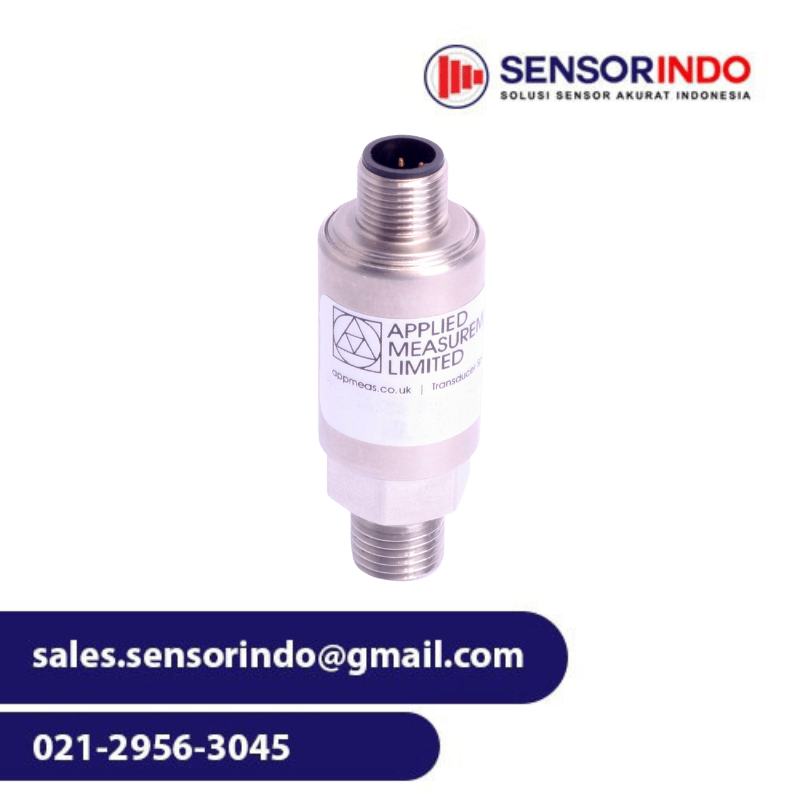
The sensor’s housing is constructed from 303 stainless steel (alternative materials including 316 stainless steel and PVDF are available) and utilises a ceramic sensing diaphragm (96% aluminium oxide Al2O3), a Viton O-ring and a G¼ inch male process connection as standard, giving the sensor an IP65 splashproof protection rating.

Thanks to its IP65 sealing, it can be used for the measurement of gas and liquid pressure in many I2C industrial applications.

We can easily accommodate any requirement from a one-off to bulk orders for many thousands of sensors, all within our in-house, UK production facility.

Alternate casing and construction materials, O-rings and process connections can all be offered, including G¼” female and ¼” NPT male connectors.  Should you require a pressure sensor tailored to your specific pressure measurement application, we can design and manufacture fully-customised sensors for you – please contact our friendly sales team to discuss your requirement in detail.

How I2C Protocol Works

I2C communication protocol uses 2 wires to transmit information between the Master and the Slave on an I2C bus, the SDA and the SCL. The Serial Data Line (SDA) carries the data bi-directionally between the Master and the Slave device. The Serial Clock Line carries the clock signal ensuring the Slave and the Master’s clock are synchronised. The Clock signal is always controlled by the Master.

Each I2C device connected to the bus has a unique address. This is used by the Master to differentiate between the various Slave devices on the I2C bus. The I2C pressure sensor works as a Slave on the bus.

I2C Bus Illustration

Benefits of an I2C Communication Bus

  • Easy to add on and remove and modify the design by easily clipping on and clipping off the I2C devices.
  • Easy to install as the I2C communications protocol is already embedded on the chip inside the sensor.
  • Simple 2-wire data transfer.
  • Easy fault finding with the unique address of every I2C connected device.
  • Low current consumption.

I2C Data Transfer Sequence

Data is transferred between the Master and the Slave in Frames making up a single Message. Each message will always begin with the START condition followed by the unique address of the I2C Slave device. Below is an example of how a Master will send data to and from an I2C Industrial Pressure Sensor.

  • The Master begins by sending a START command to the unique address ID of the Slave it wants to communicate with.
  • The Master then tells the Slave whether it wants to send data to it (WRITE) or receive data from it (READ).
  • The Slave acknowledges whether or not it has received the command. 0 = Acknowledge, 1 = Not Acknowledged.
  • Once the 0 (ACK) is received by the Master, the Master then transfers the data to the Slave in 8 bits packet.
  • The Master sends the STOP command when the data sequence has been transferred.
I2C COMMAND PROTOCOL SEQUENCE

Features

  • Ranges: 0-500mbar up to 0-700bar
  • Output: I2C
  • Environmental Protection: IP65 (IP67 optional)
  • Accuracy: <±0.25%/FS (<±0.1% optional)
  • Stainless Steel Construction
  • UK-Made
  • UK-Manufactured – Short Lead Times
  • I2C Protocol for Bi-Directional Data Transfer
  • Supports Multiple Masters and Multiple Slaves
  • IP65 Splash-Proof for Industrial Applications
  • 2 Week Delivery!
  • High Volume Production Available
  • Customised & OEM Versions

Specifications

Nominal Pressure Range Bar (gauge, absolute or sealed gauge) 0-0.5 0-1 0-2 0-5 0-10 0-20 0-50 0-100 0-250 0-400 0-600 0-700
Compound Ranges Bar - -1…0 * -1…+2 * -1…+5 -1…+9 -1...+19 -1...+29 - - - - -
Permissible Overpressure Bar 1 2 4 10 20 40 100 200 400 575 800 800
Burst Pressure Bar 2 4 5 12 25 50 120 250 500 650 950 950
*<±0.1% / FS (BFSL) accuracy not possible in these ranges
Output Signal & Supply Voltage Wiring System Output Supply Voltage Input Current
Pa6DC 4-wire I2C 2.7-5.5Vdc <3mA
Performance
Accuracy (non-linearity, hysteresis, repeatability) % Full Scale Output <±0.25 (BFSL) <±0.1 (BFSL) optional
Zero Balance ±% of Rated Output <1.0
Setting Errors (offsets) Zero & Full Scale, <±0.5% / FS
Influence Effects Supply Effects <0.005 % FS / 1V
Response Time (10% - 90%) ms ≤10
Warm-Up Time ms 500 typ.
Permissible Temperatures & Thermal Effects
Media Temperature (Note: subject to 'O' ring seal, see below) ˚C -40 to +135
Ambient Temperature ˚C -20 to +85
Storage Temperature ˚C -20 to +85
Compensated Temperature Range ˚C +20 to +80
Thermal Zero Shift (TZS) % / FS / ˚C <±0.04 (standard) <±0.02 (option) <±0.01 (option)
Thermal Span Shift (TSS) % output / ˚C <-0.015
Electrical Protection
Reverse Polarity Protection No damage but also no function
Electromagnetic Compatibility CE Compliant
Insulation Resistance Megohms Ω at 50V dc >500
Mechanical Stability
Shock 100 g / 11 ms
Vibration 10 g RMS (20 ... 2000 Hz)
Materials
Housing & Process Connection 303 Stainless Steel 316L Stainless Steel (optional)
‘O’ Ring Seals (inc. Temperature Range) Viton (-20ºC to +135ºC) NBR/Nitrile (-40ºC to +100ºC) (optional) EPDM (-40ºC to +130ºC) (optional) Chemraz (-10ºC to +135ºC) (optional)
Diaphragm Ceramic Al2O3 96 %
Media Wetted Parts Housing and process connection, ‘O’ ring seal, diaphragm
Misc
Weight grams 100 nominal
Installation Position Any
Operational Life pressure cycles > 100 x 106
Environmental Protection Cable Gland M12 x 1 Connector M12 x 1 Connector IP65 Gauge Reference ≤ 50bar : IP65 / Absolute, Sealed Gauge or >50bar Range : IP67

Product Dimensions

I2C Pressure Sensor Pa6DC M12 Outline

I2C Pressure Sensor Pa6DC M12 Outline

I2C Pressure Sensor Pa6DC Gland Outline

I2C industrial pressure sensor gland outline drawing

WIRING DETAILS

 Electrical Connection Type+ve Supply-ve SupplySDASCL
M12x1 Connector Pin 1 Pin 2 Pin 3 Pin 4
Cable Gland Red Blue Green Yellow

ORDERING CODES & OPTIONS

Pa6DCM-10barg-A4AV-00-000 Pa6D C M - 10barg - A 4 A V - 00 - 000
Product Family
Pa6D Pa6D
Electrical Output
C = I2C C
Electrical Connection / ATEX Certification
C = IP65 Cable Gland + Screened, Un-Vented PVC Cable C
M = M12x1 4-pin Connector M
MM = M12x1 4-pin Connector + Mating Half MM
Pressure Range
10barg = 0 to 10bar gauge 10barg
M1P1barg = -1 to +1bar gauge M1P1barg
P15P500psia = +15 to +500psi absolute P15P500psia
2400psig = 0 to 2400psi gauge 2400psig
Accuracy (Non-Linearity & Hysteresis)
A = <±0.25%/FS (standard) A
B = <±0.1%/FS B
Zero Temperature Compensation (TZS)
4 = <±0.04%/FS/ºC 4
2 = <±0.02%/FS/ºC 2
1 = <±0.01%/FS/ºC 1
Continued on next page
Process Connection
A = G¼” Male DIN 3852 in 303 St/Steel A
B = G¼” Male DIN 3852 in 316L St/Steel B
C = ¼” NPT Male 303 St/Steel C
D = 7/16 UNF-20 Male D
E = G¼” Female in 303 St/Steel E
F = G¼” Male DIN 3852 in PVDF (Polyvinylidene Fluoride) F
S = 9/16 UNF Internal (no bleed hole) S
O-Ring Material
V = Viton (FKM) V
N = Nitrile (NBR) N
E = EPDM (Ethylene Propylene Diene Monomer) E
C = Chemraz (Perfluoroelastomer) C
Cable Length (in metres)
00 = None 00
01 = 1 metre 01
Specials Code
000 = No Special Requirements 000
010 = Cleaned for Oxygen Service 010

I2C (I²C) COMMUNICATION INFORMATION

I2C Slave Default address: 00 Clock Frequency: 400 kHz
Data is 24 bit unsigned absolute value NOTE: Address Values in Hex
Calibration Data Memory Locations
16 bit Device Serial Number: ● NVM Address 00: bits 0 to 15 (LSB) ● NVM Address 01: bits 16 to 23 (MSB)
16 bit Device Zero Pressure Range: ● NVM Address 2A: bits 0 to 15 24 bit Corrected ZERO calibration reading: ● NVM Address 24: bits 0 to 15 (LSB) ● NVM Address 25: bits 16 to 23 (MSB)
16 bit Device Full Scale Pressure Range: ● Address 2C: bits 0 to 15 24 bit Corrected FULL SCALE calibration reading: ● NVM Address 26: bits 0 to 15 (LSB) ● NVM Address 27: bits 16 to 23 (MSB)
16 bit Device Zero Decimal Place: ● NVM Address 2B: bits 0 to 15 16 bit Device Full Scale Decimal Place: ● NVM Address 2D: bits 0 to 15
16 bit Device Pressure Engineering Units: ● Address 29: bits 0 to 15 0001 - mbar 0002 - Bar 0003 - Psi
16 bit Device Pressure Datum Type: ● Address 2E: bits 0 to 15 0000 - Gauge 0001 - Absolute 0002 - Sealed Gauge
Reading a Memory Location
To get the data, read out 3 bytes: ● Byte 1 = Status byte (If not required, ignore) ● Byte 2 = NVM Memory data (bits 15:8) ● Byte 3 = NVM Memory data (bits 7:0) Example: Serial number read: 71652 00Hex = LSB = 17E4 01Hex = MSB = 1
Reading the Pressure Data To read a register use the memory location as the command
To initiate a pressure reading use one of the following commands: ● A single reading command: AAhex ● An average of 4 consecutive readings : ADhex ● An average of 8 consecutive readings : AEhex
To acquire pressure data read 4 bytes: ● Byte 1 = Status byte (ignore) ● Byte 2 = Sensor data (bits 23:16) ● Byte 3 = Sensor data (bits 15:8) ● Byte 4 = Sensor data (bits 7:0)

Note: data is only available once per issuance of a read command.

Below is an example of a 0 to 10 Bar absolute pressure range, the NVM would look like this:

  • 2A (Zero pressure range) = 0000
  • 2B (Zero decimal place) = 0000
  • 2C (Full scale pressure range) = 000A
  • 2D (Full scale decimal place) = 0000
  • 29 (Pressure engineering units) = 0002
  • 2E (Pressure datum type) = 0001

An example of typical calibration figures would look something like this:

  • 24 (Zero calibration LSB) = 4563
  • 25 (Zero calibration MSB) = 0019
  • *When converted from HEX, 0019 4563 to decimal = 1656163
  • 26 (Full scale LSB) = 4C8E
  • 27 (Full scale MSB) = 00E6
  • *When converted from HEX, 00E6 4C8E to decimal = 15092878

This, therefore, means that 0 Bar Absolute pressure = 1656163 and 10 Bar absolute pressure = 15092878 giving a span of 13436715 for 10 bar.

Reviews

There are no reviews yet.

Be the first to review “I2C Pressure Sensor | Pa6DC”

Your email address will not be published. Required fields are marked *