Description
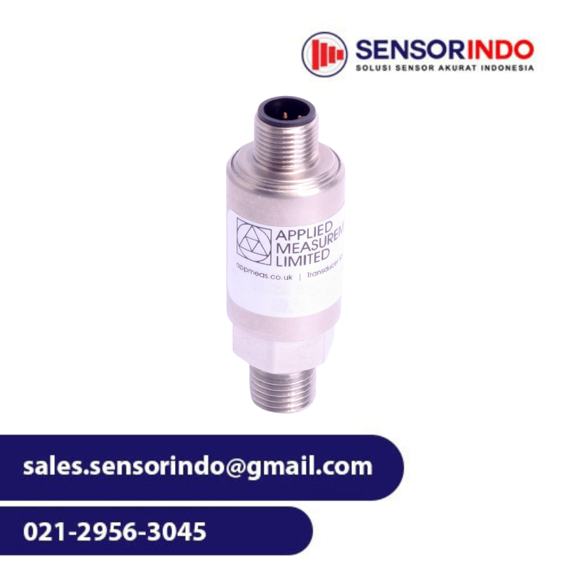
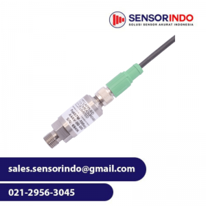
Applied Measurements I2C pressure sensor Pa6DC uses an I2C (Inter-Integrated Circuit) protocol to communicate with the Master Controller. The I2C output is ideal for OEM, machine feedback systems, control systems and automation applications.
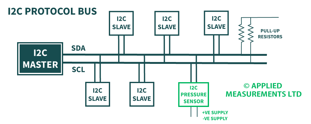
The benefit of using a pressure sensor with an I2C interface is that can be supported along with many I2C devices on the same circuit. I2C protocol allows an unlimited number of master devices to communicate with a maximum of 1008 slave devices on the bus. For example one Master with one Slave, multiple Masters with a single Slave, a single Master with multiple Slaves, or a Multi-Master with multiple Slaves. The I2C gas pressure sensor is designed to work as a Slave on an I2C protocol bus.
As with I2C devices, the I2C pressure sensor uses only 2 wires to transmit data between the devices on the system (2 further wires are required from the pressure sensor for the +ve and -ve supply, see I2C protocol diagram below).
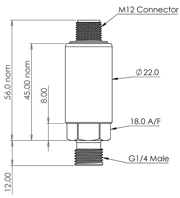
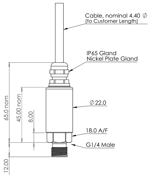
The sensor’s housing is constructed from 303 stainless steel (alternative materials including 316 stainless steel and PVDF are available) and utilises a ceramic sensing diaphragm (96% aluminium oxide Al2O3), a Viton O-ring and a G¼ inch male process connection as standard, giving the sensor an IP65 splashproof protection rating.
Thanks to its IP65 sealing, it can be used for the measurement of gas and liquid pressure in many I2C industrial applications.
We can easily accommodate any requirement from a one-off to bulk orders for many thousands of sensors, all within our in-house, UK production facility.
Alternate casing and construction materials, O-rings and process connections can all be offered, including G¼” female and ¼” NPT male connectors. Should you require a pressure sensor tailored to your specific pressure measurement application, we can design and manufacture fully-customised sensors for you – please contact our friendly sales team to discuss your requirement in detail.
How I2C Protocol Works
I2C communication protocol uses 2 wires to transmit information between the Master and the Slave on an I2C bus, the SDA and the SCL. The Serial Data Line (SDA) carries the data bi-directionally between the Master and the Slave device. The Serial Clock Line carries the clock signal ensuring the Slave and the Master’s clock are synchronised. The Clock signal is always controlled by the Master.
Each I2C device connected to the bus has a unique address. This is used by the Master to differentiate between the various Slave devices on the I2C bus. The I2C pressure sensor works as a Slave on the bus.
Benefits of an I2C Communication Bus
- Easy to add on and remove and modify the design by easily clipping on and clipping off the I2C devices.
- Easy to install as the I2C communications protocol is already embedded on the chip inside the sensor.
- Simple 2-wire data transfer.
- Easy fault finding with the unique address of every I2C connected device.
- Low current consumption.
I2C Data Transfer Sequence
Data is transferred between the Master and the Slave in Frames making up a single Message. Each message will always begin with the START condition followed by the unique address of the I2C Slave device. Below is an example of how a Master will send data to and from an I2C Industrial Pressure Sensor.
- The Master begins by sending a START command to the unique address ID of the Slave it wants to communicate with.
- The Master then tells the Slave whether it wants to send data to it (WRITE) or receive data from it (READ).
- The Slave acknowledges whether or not it has received the command. 0 = Acknowledge, 1 = Not Acknowledged.
- Once the 0 (ACK) is received by the Master, the Master then transfers the data to the Slave in 8 bits packet.
- The Master sends the STOP command when the data sequence has been transferred.


